
Cascade Jet Nozzles are precision devices used to direct controlled air or fluid streams across surfaces, openings, or process zones. Their design combines several small passages, arranged in a cascade, to create a stable and evenly distributed jet pattern. This arrangement can improve cooling, drying, cleaning, mixing, and material handling performance.
Dr. David G. Bogard, a recognized researcher in jet impingement cooling, states, “The effectiveness of a jet depends on how well its momentum reaches the target surface.” That principle explains why nozzle spacing, outlet geometry, pressure, and stand-off distance matter. A nozzle may look simple, yet small dimensional changes can alter turbulence, velocity, and coverage. Even a slightly misaligned outlet can leave a visible cold or dry patch.
Inside Cascade Jet Nozzles, pressurized air enters a manifold and divides through multiple channels. Each channel shapes the flow before it exits through a narrow opening. The resulting jets may merge, overlap, or remain separated, depending on the operating conditions. Engineers usually evaluate pressure loss, flow uniformity, noise, temperature, and maintenance access.
Real-world performance is rarely perfect. Dust can obstruct narrow passages. Uneven supply pressure can weaken one section. Poor installation can undermine an otherwise excellent design. For that reason, reliable selection requires field measurements, not catalog claims alone. This guide examines how Cascade Jet Nozzles work, where they perform best, and which practical details deserve closer attention.
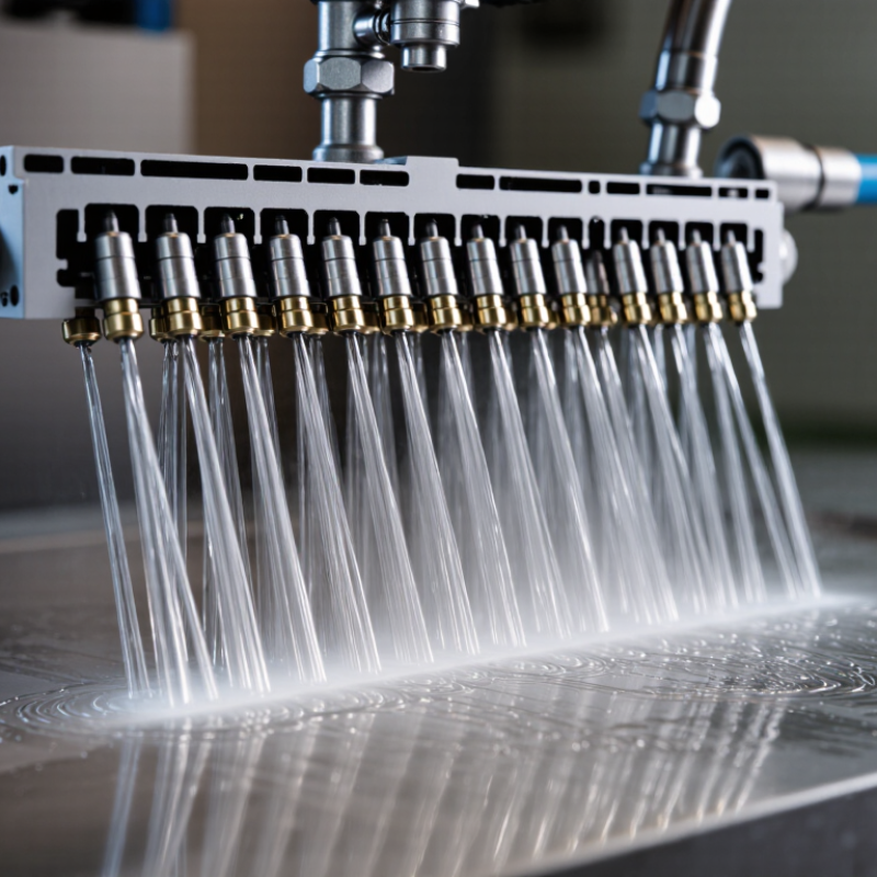
Cascade jet nozzles are fluid-control devices that release liquid or gas through several aligned openings. Their name comes from the cascading flow pattern produced by staged passages. Unlike a single-port nozzle, this design divides one supply stream into smaller, controlled jets.
The basic structure usually includes an inlet, internal distribution chamber, flow passages, and an outlet plate. The inlet connects to a pressurized pipe. Inside the chamber, the fluid spreads before entering narrow channels. Each channel guides the flow toward a final opening. Some models use stepped plates or layered inserts. These parts create multiple jet levels and help shape the discharge pattern.
Pressure differences drive the fluid through the nozzle. As the passages become narrower, velocity usually increases. The outlet geometry then determines whether the jets form a sheet, spray, or separated streams. In practical inspection, uneven spacing can reveal blockage or poor alignment. Small particles may disturb the pattern quickly. Cleaning access matters more than many basic diagrams suggest.
Performance depends on pressure, fluid viscosity, passage size, and temperature. Engineers often check flow rate, spray angle, noise, and vibration during testing. A cascade design can improve distribution, but it is not automatically more efficient. Poor internal balancing may cause one jet to dominate. That detail is easy to overlook. Real installations also need compatible seals, stable mounting, and regular inspection.
A cascade jet nozzle uses a sequence of internal passages or deflectors to divide, guide, and accelerate a fluid stream before it exits through the outlet. The chart shows the ideal air-jet velocity associated with several pressure differentials. Values are calculated using the ideal relation v = √(2ΔP/ρ), assuming air density of 1.20 kg/m³; actual nozzle velocity depends on geometry, temperature, turbulence, and discharge losses.
In a real cascade jet nozzle, the inlet receives pressurized air, the cascade passages redistribute and straighten the flow, and the outlet converts pressure energy into a focused jet. The ideal velocity rises with pressure differential, while internal losses make measured performance lower than the theoretical values shown here.
Cascade jet nozzles use staged internal passages to shape fluid into controlled, overlapping jets. Their performance depends on several small components, not only the visible outlet.
The nozzle body provides structural support and guides the incoming air or water. A threaded inlet connects the unit to the supply line. Inside, the cascade chamber divides the flow through stepped channels. These channels reduce turbulence and distribute pressure more evenly. The final orifice converts that controlled pressure into a narrow, high-velocity jet. A seal prevents leakage around the connection, while a mounting bracket keeps the spray angle stable during operation.
The inlet pressure controls available energy. The orifice diameter controls flow volume and jet speed. A smaller opening usually produces a sharper stream, but it may clog more easily. According to the U.S. Department of Energy’s Compressed Air System Best Practices, compressed air can represent about 10% of industrial electricity use, while leakage may waste 20–30% of compressor output. This makes sealing and pressure selection practical cost issues, not minor details. The European Commission’s Industrial Emissions reference documents also emphasize efficient fluid control in process equipment. Actual results still vary with temperature, viscosity, and pipe length. That part is easy to underestimate. In field inspections, a slightly misaligned nozzle can leave dry spots, uneven cooling, or noisy turbulence. Regular cleaning, pressure checks, and flow measurement in L/min help confirm whether each component is performing as intended.
| Main Component | Typical Material or Feature | Individual Function | How It Supports Cascade Operation | Important Design Considerations |
|---|---|---|---|---|
| Inlet Connection | Threaded, flanged, compression, or welded connection | Provides the entry point for the pressurized fluid and connects the nozzle to the supply pipe or manifold. | Maintains a sealed and stable feed so the downstream stages receive a consistent supply. | Connection size, pressure rating, sealing method, and compatibility with the process fluid must be checked. |
| Inlet Chamber | Internal chamber with a comparatively larger flow area | Receives incoming fluid and reduces abrupt disturbances before the fluid reaches the restriction or distribution stages. | Helps provide more uniform pressure around the internal flow passages. | Chamber volume and geometry influence pressure stability, residence time, and the risk of stagnant zones. |
| Flow-Conditioning Passage | Machined channel, guide vane, or shaped internal passage | Aligns, redirects, or conditions the flow before it enters the next stage. | Reduces uneven loading between outlet jets and supports a repeatable spray or discharge pattern. | Sharp turns can increase turbulence and pressure loss; smooth transitions generally improve efficiency. |
| Primary Restriction | Orifice, slot, throat, or engineered constriction | Converts available pressure into controlled velocity and limits the flow entering the cascade stages. | Establishes the initial pressure drop that drives the fluid through the successive passages. | Orifice diameter, edge quality, and fouling resistance strongly affect flow rate and wear. |
| Cascade Stages | Two or more sequential chambers, steps, or internal passages | Distribute pressure reduction and flow redirection across several stages instead of one abrupt transition. | Creates the characteristic cascading flow path and can improve jet uniformity while controlling turbulence. | Stage count, passage alignment, and pressure ratio must match the required flow and discharge pattern. |
| Interstage Chamber | Intermediate cavity between restriction stages | Allows the fluid to expand, redistribute, and stabilize before entering the following restriction. | Balances flow between multiple paths and moderates the pressure change from one stage to the next. | Insufficient volume may cause uneven distribution; excessive volume can increase size and residence time. |
| Jet-Forming Orifices | Precision-drilled holes, slots, or replaceable inserts | Convert the conditioned flow into individual jets with defined direction and approximate flow rate. | Determine the number, spacing, angle, and overall coverage of the final cascade pattern. | Orifice size, outlet angle, surface finish, and wear resistance affect jet quality and consistency. |
| Outlet Face or Nozzle Tip | Flat, angled, profiled, or removable discharge face | Provides the final exit geometry and directs the jets toward the target surface or process zone. | Controls the external spread, impact location, and overlap between neighboring jets. | Tip alignment, outlet spacing, and clearance from the target are important for uniform coverage. |
| Gaskets and Seals | Elastomer, polymer, graphite, or metal sealing elements | Prevent leakage at joints, removable tips, and interfaces between nozzle sections. | Preserve the intended pressure distribution inside the cascade passages. | Seal material must tolerate the operating temperature, pressure, chemicals, and cleaning method. |
| Mounting Body or Holder | Rigid housing with mounting holes, clamps, or brackets | Supports the nozzle and maintains its position relative to the pipework and target. | Keeps the outlet pattern correctly oriented so the cascade jets remain properly aligned. | Mechanical loads, vibration, thermal expansion, and access for maintenance should be considered. |
| Optional Strainer or Filter | Mesh, perforated screen, or upstream filtration assembly | Removes particles that could block small internal passages or outlet orifices. | Helps maintain stable flow and consistent jet performance over time. | Filter size must balance particle protection against pressure loss and cleaning frequency. |
| Inspection and Cleaning Access | Removable cover, service plug, or detachable nozzle tip | Allows internal passages and outlet openings to be inspected, flushed, or replaced. | Restores the designed cascade pattern when deposits or debris affect the flow. | Access should permit safe isolation, drainage, cleaning, and reassembly without damaging precision surfaces. |
A cascade jet nozzle begins when pressurized fluid enters its inlet chamber. The chamber reduces sudden pressure changes and distributes flow across internal passages. This stage matters. Uneven pressure can create weak jets, vibration, and inconsistent coverage. Engineers check the inlet pressure, fluid temperature, and nozzle material before operation.
The fluid then moves through several openings arranged in levels or channels. Each opening forms a narrow jet. These jets travel at controlled angles, creating a layered or cascading pattern. As the streams leave the nozzle, they may overlap slightly. That overlap improves surface coverage and helps spread energy more evenly. In cleaning systems, the moving fluid reaches a surface and loosens deposits. In cooling or spraying systems, it transfers heat or moisture across a wider area.
The process is not always perfectly uniform. Small particles, worn openings, or trapped air can disturb the pattern. Field inspections often reveal this before performance drops noticeably. Operators should observe the jet shape, listen for unusual noise, and compare flow readings with expected values. A practical test uses a clean collection tray beneath the nozzle. Unequal volumes suggest blockage or pressure imbalance. The exact result depends on fluid density, pump capacity, opening size, and installation angle. That last factor is easy to underestimate. Careful adjustment usually produces better coverage than simply increasing pressure.
Cascade jet nozzles guide fluid through several aligned passages before it leaves the outlet. Each passage reshapes the flow, creating layered jets that may merge downstream. The final pattern depends on pressure, channel geometry, and the distance to the target surface. At low pressure, the streams can look uneven. At higher pressure, they usually become more coherent, but turbulence and noise may increase.
Flow distribution is a key performance characteristic. A well-designed nozzle delivers similar velocity across its outlet width. This helps produce consistent cooling, cleaning, mixing, or surface coverage. Engineers often check volume flow, pressure loss, spray angle, and jet stability during testing. The result is visible. A stable cascade pattern forms a controlled sheet or group of narrow streams, rather than random splashing.
Actual performance can change with temperature, fluid viscosity, and small deposits inside the passages. Installation alignment also matters more than many test reports suggest. A nozzle placed only a few millimeters off-axis may create uneven impact on the target. Computational models can predict pressure and velocity, but they cannot fully represent every rough edge or blocked channel. A clean calculation can still mislead. Reliable evaluation combines measurements, visual inspection, and repeated tests under working conditions. I would also question any result based on one pressure setting, because real systems rarely operate so perfectly.
What Are Cascade Jet Nozzles and How Do They Work?
Cascade jet nozzles use several air streams to create a wider, faster-moving jet. The primary flow pulls surrounding air into the discharge. This increases coverage without proportionally increasing compressed-air demand. In practical terms, the nozzle can resemble a narrow metal bar mounted above a conveyor, producing an even air curtain across bottles, sheets, or molded parts.
Industrial applications depend on the required force, distance, and operating environment. Plants use cascade nozzles for drying, cooling, cleaning, blow-off, and removing dust from moving products. The U.S. Department of Energy reports that compressed-air systems can consume about 10% of industrial electricity, so nozzle efficiency deserves serious attention. A poorly selected design may create excessive noise, uneven drying, or hidden energy losses.
Selection should begin with air pressure, flow rate, target width, product speed, and nozzle-to-surface distance. ISO 8573 air-quality classes also matter when air contacts food, pharmaceuticals, or sensitive surfaces. The IEA’s Energy Efficiency 2023 report identifies industry as one of the largest global energy-consuming sectors, making small pneumatic improvements worthwhile. Still, laboratory figures can mislead. Real factories have leaks, fluctuating pressure, and imperfect alignment. Test the nozzle on the actual line, measure flow and sound levels, then compare results under normal production conditions. There is no universal best nozzle.
It guides pressurized fluid through several aligned openings. These openings create layered jets at controlled angles.
Pressurized fluid enters an inlet chamber. The chamber reduces sudden pressure changes and distributes flow across internal passages.
Uneven pressure can produce weak jets, vibration, and inconsistent coverage. Engineers also check temperature and nozzle material.
Narrow streams leave in layers and may overlap slightly. This creates a broader, more even coverage pattern.
Pressure, channel shape, fluid viscosity, temperature, and target distance all matter. Installation angle matters too.
They can inspect the jet shape, listen for unusual noise, and compare flow readings. A clean collection tray helps reveal unequal volumes.
No. Higher pressure may make streams more coherent, but turbulence and noise can increase. More pressure is not always better.
Models may miss rough edges, trapped air, or partly blocked channels. One pressure test can give false confidence.
Even a few millimeters off-axis can shift the impact area. Careful adjustment often works better than increasing pressure.
It should combine flow measurements, visual inspection, and repeated tests under working conditions. Real systems are rarely perfect.
Cascade Jet Nozzles are specialized fluid-delivery devices designed to produce a controlled, layered spray or cascading flow. Their basic structure typically includes a body, inlet passage, internal flow channels, discharge openings, and mounting connections. Each component has a specific role: the body provides mechanical support, the inlet guides the incoming medium, the channels divide and redirect flow, and the outlets shape the final spray pattern. Together, these parts help maintain stable distribution and consistent coverage.
During operation, fluid enters through the inlet, moves into the internal channels, and is divided into several streams before exiting through the discharge openings. The resulting flow may form overlapping sheets, curtains, or multiple directed jets, depending on the nozzle geometry and operating conditions. Performance is influenced by pressure, flow rate, viscosity, temperature, and outlet design. Cascade Jet Nozzles are commonly considered for cooling, cleaning, coating, rinsing, and process-control systems. Proper selection requires matching the nozzle material, capacity, spray pattern, installation angle, and maintenance needs to the intended industrial application.